|
Piece Editing |
  
|
|
Piece Editing |
|
The Piece Editor allows you to manipulate individual pieces of PartyCAD furniture. To access the menu, select a piece in the Design Editor and then click File > Edit Piece
Another way to get to the menu is from the Start Menu, where you can click Options > Advanced Options > Edit 'My Library' Piece. This is a special way of working with the menu, called Special Piece Editing, which allows you to mirror a piece of furniture, or to load a DXF file created outside of PartyCAD. There are certain pieces of furniture that are nearly impossible to create within the package. Usually these are curved in three dimensions, something like a resin chair. Special Piece Editing allows you to import such pieces from more capable 3D modeling packages such as 3D Canvas, Milkshape and a dozen others.
Standard Piece Editing
The most common use of the Piece Editor it to change the coloration of already existing pieces of furniture. Take a look at these three table/chair sets:
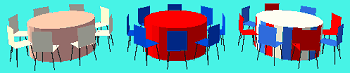
The left-most is just a 5RT8C (five-foot round table with 8 chairs) from the furniture library.
One of the first things you probably learned in PartyCAD was how to change default colors by clicking the color bar at the upper-left corner of the Design Editor. Doing so, you can quite easily get the middle version of the table and chairs above.
The third version of the tables and chairs is a recoloring of a standard 5RT8C done with the Piece Editor. The Piece Editor gives you control over the color of every facet of a piece.
Here is how it is done:
Begin in the Design Editor by clicking on the piece you wish to edit. You can group together a bunch of pieces and edit them as a group, if you like, but what the Piece Editor will return is a welded-together version of the group. (The original group will be left intact and the welded version will be loaded as a new piece rather than as a modification of your original, as it done for simple pieces.)
For now, select just a single piece, say a 5RT8C, and in the Design Editor, click File > Edit Piece. The piece will be loaded into the Piece Editor and will look something like this:
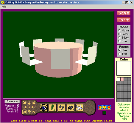
Since the Piece Editor is most often used to change the colors of pieces, it comes up all ready to do this. In this mode (Faces/ Color) lines such as the legs of the chairs in the piece above are not displayed. They are still in there, though, and you could, if you like, click the Normal radio button to see the piece just as it would be displayed in the View Editor.
The navigation controls beneath the picture are very similar to those in the View Editor. The only real difference is that dragging on the picture causes the piece to rotate. To "walk," drag on the footsteps button located beneath the picture. Right drag on this same button to slide from side to side.
Clicking the Remember button saves the current view. If you do this a Restore button will appear. You can click then click Restore at any time to return to the saved view of your piece.
The buttons to the right of the navigation bar are used to position the sun and lock it in place. Again, these work the same as in the View Editor.
The colored box below the "sun controls" allows you to set the background color of the picture.
At the right of the picture are controls that vary depending on the selected mode. The picture above is what you see in Faces/ Color mode, where you can change the colors and textures of the faces of the model.
Selecting Stuff
The various modes are explained later on. Before discussing them, let's look at the ways of selecting things within the picture of the model.
1. Dragging with the left mouse button on the background rotates the piece of furniture. Dragging on the stepladder button, especially dragging with the right mouse button, is useful for viewing the top and bottom of the piece.
2. Clicking on a facet or line in the picture will cause it to be colored, typed, shown or hidden depending on the current mode at the right of the screen.
3. Dragging with the right mouse button will cause a box to appear. All facets or lines that are completely within the box when you release will be colored, typed, shown or hidden. This is just the same as clicking but the operation will be performed on many items instead of just one. This can be a real time saver when working on complex models.
4. Holding the Ctrl Key and clicking on a line in Edges or Icon mode will select all the edges at the same height as the line you have selected. Again, this can be very useful when working on complex models.
Coloring Your Models
When in Faces/ Color mode, a color box appears to the right of the picture. You use this to select colors and textures.
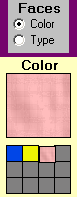
To add a new color just click on an unused small button below the big box showing the current color. Once you have selected the color you want, click on the model to begin coloring. You can change an existing color by right-clicking on its button. This brings up the Texture/Color Selection menu where you can select a new color or material to replace the old one.
To quickly paint an entire model with one color, first selecting the color and then right dragging a box around the entire model in the picture.
Once you have things looking the way you want them, just click the big, red Save button and your modified model will be loaded onto the Design Editor.
Fancier Editing
The Piece Editor can do much more than just color your pieces, but it is important to understand how PartyCAD's pieces are constructed before proceeding. Let's talk about that now.
About PartyCAD's Models
A piece of PartyCAD furniture begins with geometry. This is the part that can be imported from DXF files. The geometry of each piece consists of vertices, edges and facets. Facets are sometimes called faces.
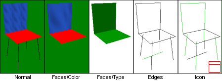
--- A vertex is a point in 3D space. For instance, in the Normal view above, notice the place where the front chair leg ends near the bottom of the picture. That point is a vertex. If you look at the Edges view of the chair, you may be able to count all 16 of its vertices. The Piece Editor does not currently allow you to modify the vertices of models in any way.
--- An Edge is a line connecting two vertices. Again, you may be able to count the edges in the Chair in the Edges view above. There are 12 of them.
--- A Facet is a group of edges that enclose a flat portion of 3D space. In the model about there are just 2 facets. Color and texture can be applied to a facet but not to an edge or vertex. Colors are obvious, but textures require a little explanation. A texture is a bitmap(BMP), JPG or PNG image that is applied to the area enclosed by a facet. The image can be stretched to fit the facet. To do this you select Max as the repeat distance when specifying the texture. Look at the blue back of the chair in the Faces/Color picture above. Here the SATIN texture has been applied with a Max repeat. Alternatively, you can specify a repeat distance for a texture. In the Normal view above, the SATIN texture has been applied with a 6" repeat. You can learn about importing your own textures by clicking here. (For a list of free online textures sites, Google: Free tiling textures library.)
So far, so good. Vertices, edges and facets are a part of any 3D model. In PartyCAD there are two additional things to worry about due to the use the program makes of such models.
--- Edge Visibility - The View Editor creates line drawings based on the geometry of the piece. The lines that it displays are just the edges of the model, with some lines or parts of lines being blocked by the facets of the model. Sometimes however, you will not want every possible line to be drawn in the View Editor, and thus each edge has a visibility attribute that you can manipulate using the Piece Editor. Think about the roof of a canopy tent. There might be hundreds of edges involved in representing this complex curved shape in 3D, but if all of them were to be shown when line drawings were created, it would look awful. The solution is to hide most of the edges, just keeping enough to give an idea of the shape of the tent top. In the Edges view above, the lines that show in the View Editor are black, the hidden ones are in green.
--- Icon Lines - In order to create nice looking furniture arrangements in the Design Editor, each piece of PartyCAD furniture must be supplied with an icon that will represent it in plan views. Icons are often just selected edges in the actual model, but sometimes additional lines are added using the Design Editor to specifically be a part of the icon of a piece. Look at the one hidden edge in the Edges view above. The only reason this edge is in the model is to serve as part of the icon for the piece. You can see this in the Icon view, where the black lines indicate lines that are a part of the icon for the chair. The red figure in this view shows what the icon for the piece will look like in the Design Editor. Just imagine looking straight down on the model and you will see how the icon was created from the 3D model. In order for the Design Editor to perform as expected, it is important that the icon of a piece include at least lines around its perimeter when viewed from the top. The Piece Editor cannot add edges specifically for use as icon lines, but as mentioned above, such lines can be added in the Design Editor.
OK. Now we are ready to talk about the Piece Editor's other modes. Faces/ Color was already covered above.
Modes of Operation

At the top right of the screen, radio buttons allow you to select the editing mode of the Piece Editor. Normal mode displays the model as it will appear in the View Editor and is usually used to check a model just before saving.
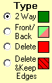
Clicking the Faces mode button and the Type sub-mode button displays the controls above. These are used to set the type of the faces in the model, which can speed hidden line removal in complex pieces. PartyCAD furniture and models from DXF files always start out with 2 Way faces. Generally this will be fine for any model you make, but if your are curious, read on.
Think about one of those monsters you have seen in a computer video game. Some have 1000 faces, and any way we can think of to speed their rendering is worth looking into. One such way is to only render faces that are faced toward the camera. That way all the faces on the far side of the model can be ignored. Think of a box made of 2-Way faces. If you walk inside the box you will still see the faces because they are visible from either side. Now think of that same box made with 1-Way faces. When viewed from the outside, the box will look just the same, though it will render more quickly because the faces pointed away from you are skipped. (You won't notice the difference in rendering speed on something as simple as a box.) Now walk into this 1-Way box. It will seem to disappear. This is because from the inside, you will always be looking at the back of 1-Way faces.
If you want to mess around with this, select the Front/Back option and start marking up faces, then switch to Normal mode and walk into the model to see how the 1-way faces perform.
Deleting Faces - A more frequently used capability of Faces/Type mode is the ability to delete faces. This can come in very handy. Faces you delete will not show in the Normal or Faces/Color views of the model. The upper Delete button marks all the edges of the deleted faces as hidden, whereas the lower version will delete the faces but retain the edges of those faces as visible components of the model. This is sort of like changing the faces to be panes of glass. Deleted faces are just hidden in the editor, but when you save your model they are not written to disk and are then truly gone forever.


These final two modes of operation were pretty well described above in the topics on Edge Visibility and Icon Lines. Every edge in the model is marked for visibility in both 3D views and in icons. That is the reason there are two menus.
Selecting Flip means the edges you click will have their visibility flipped --- that is, if they are hidden, they will be made visible and vice-versa.
The Preview box allows you to preview the line drawing of the model or its icon as you work --- what you see is what you get, but if you accidentally hide an edge, turn off previewing so you can see a hidden edge so you can get it back.
From PartyCAD's Start Menu, if you click Options > Advanced Options > Edit 'My Library' Piece, the Piece Editor starts in a special way that allows you to modify pieces of furniture that have already been saved to disk, or to import DXF models created with other programs. When you run the Piece Editor in this way, this file selection menu will appear:
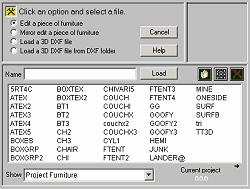
Here, various radio buttons control what files are displayed and how they will be loaded into the Piece Editor:
Edit a Piece of Furniture
If you select this radio button, the furniture files in your My Furniture Library are displayed. The editor can work on any of the files listed, but those that are grouped pieces will be saved as simple (permanently combined) pieces by the editor.
Mirror Edit a Piece of Furniture
This is similar to the above except that a mirror image of the file you select is loaded into the editor. This is useful when you have created a right-hand version of a piece and need a quick way to make the left-handed counterpart.
Load a 3D DXF File
These options allow you to load a DXF file created with AutoCAD or any other 3D CAD programs that is capable of saving a 3D model in DXF format. One inexpensive program that I like is called 3D Canvas (Google: 3D Canvas to find the website.)
All that is imported from such files is the geometry of the model. One of the main uses of the Piece Editor is to add additional information to the geometry so the model can be used within PartyCAD. This whole business of importing DXF files can be very tricky.
Once you have loaded your special piece, you can proceed to edit it as described in the previous sections. Once you have made the desired changes, click File/ Save as.. to save the piece to disk for use by the Design Editor.
Thumbnails
For most pieces, I would recommend using the simpler method of thumbnail creation described elsewhere in this help file. However, if you are a glutton for punishment, here is how to do it the hard way:
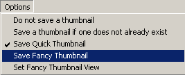
The Options button in the menu bar of the Piece Editor contains options that tell the module how to create a thumbnail for the pieces you save by clicking File > Save or File > Save as…
Select the Do not save a thumbnail option if one already exists for the piece you are about to save and you don't want to overwrite it.
Select Save Quick Thumbnail if the thumbnail is to be created from the image of the piece on the screen when you click File > Save. Just be sure a nice view is displayed at the center of the screen before you save, and you should get good results.
Select Save Fancy Thumbnail if you have taken the time to set up the view to be used for the thumbnail using the option below.
Set Fancy Thumbnail throws the program into a special mode that allows you to set up a square view of your model. When you get it right, click OK and then "check" the option just above prior to saving.