|
Draw Menu |
  
|
|
Draw Menu |
|
Watch the Drawing on the Design online video.
Clicking ![]() the Add Drawn Part button in the Design Editor brings up the Drawing menu. Here you can add lines, figures, arrows and dimensions to your design.
the Add Drawn Part button in the Design Editor brings up the Drawing menu. Here you can add lines, figures, arrows and dimensions to your design.
The menu can also be used to create 3D furniture.
Although you will probably be doing most of your drawing on a top view of your design, you can also switch to a front or side view prior to clicking the button. This allows you to create vertically oriented lines on objects in your designs. Use View From in the Menu Bar to change to a front or side view.
The Drawing menu is organized into 3 areas. At the left, the current drawing mode is displayed, along with instructions on how to proceed. In some drawing modes, a control box will also appear here.
At the right are buttons that control how your drawing is saved. It is here you can decide if simple lines or piece of 3D furniture is to be created.
The most prominent feature of the Drawing menu are the many control buttons along its top:
![]()
Buttons at the left are used to select the drawing mode. A green bar appears under the currently selected mode. In the illustration above, Arc drawing has been selected.
Here is a brief description of all of the buttons along the top of the Drawing menu:
![]() Draw Line - This button is used to draw simple lines and works differently than the other drawing buttons. Just click the button and then click and drag as many simple lines as you wish in the drawing area of the screen. By using
Draw Line - This button is used to draw simple lines and works differently than the other drawing buttons. Just click the button and then click and drag as many simple lines as you wish in the drawing area of the screen. By using ![]() the Select Line button (described below), such lines can be selected for editing at a later time. When you do this, circular red "handles" will appear at the start and end points, and can be dragged to adjust the length and position of a line. Once you are happy, click another button in the button bar to select another drawing mode, or just right-click and begin a new line.
the Select Line button (described below), such lines can be selected for editing at a later time. When you do this, circular red "handles" will appear at the start and end points, and can be dragged to adjust the length and position of a line. Once you are happy, click another button in the button bar to select another drawing mode, or just right-click and begin a new line.
![]() Draw Box - This button is used to draw a rectangular box on the screen. The first two points you click establish one edge of the box. Clicking a third point sets the distance to the opposite edge. The best way to become comfortable with this and all the drawing commands is to create a figure and drag on the handles to dynamically modify the figure. As with all the drawing commands, once you are happy, right-click to make another of the same type (another box in this case) or click another button on the button bar at the top of the screen. When you are done drawing, click one of the Save buttons at the right of the screen.
Draw Box - This button is used to draw a rectangular box on the screen. The first two points you click establish one edge of the box. Clicking a third point sets the distance to the opposite edge. The best way to become comfortable with this and all the drawing commands is to create a figure and drag on the handles to dynamically modify the figure. As with all the drawing commands, once you are happy, right-click to make another of the same type (another box in this case) or click another button on the button bar at the top of the screen. When you are done drawing, click one of the Save buttons at the right of the screen.
![]() Draw Polyline - A polyline is just a series of connected straight lines. To create such a line, click the Draw Polyline button and then click a series of points in the drawing area. After you click the second point, a control box will appear at the left of the screen:
Draw Polyline - A polyline is just a series of connected straight lines. To create such a line, click the Draw Polyline button and then click a series of points in the drawing area. After you click the second point, a control box will appear at the left of the screen:
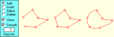
The contents of the control box vary depending on the current status of the polyline you are drawing. Initially you will be in Add mode, which says that every time you click in the drawing area, you wish to add another line segment to the end of the polyline. While in this mode, the program will beep if you attempt to click on any existing handle of the polyline. If you select Insert mode, you can click on any existing line of the polyline to insert another handle at that point. After the handle has been inserted, the program automatically switches to Adjust mode, where you can drag on any of the handles to adjust the shape of your polyline. Finally, if you select Delete mode, you can click on any handle of the polyline to remove it.
A Hint - If the program starts beeping when you click in the drawing area, generally this means you are not in the mode you think you are. Check the selection at the left, fix it and try again.
Two checkboxes at the bottom of the Polyline control box extend the usefulness of polylines. The first of these is the Close checkbox. Checking this causes the program to automatically add a line from the last control point you clicked, back to first one, thus closing the figure. See the second illustration above. You will find this very useful, as you cannot manually close a polyline by clicking on the first handle.
The other option is the Smooth checkbox. Checking this causes some magic to happen as the program converts the straight lines connecting your handles to a smooth spline curve. This is very nice indeed when you want to create smooth looking curves in your design. Closed, smoothed figures are great for kidney shaped pools and for blobs that will contain explanatory text. In drawing the spine line, the program attempts to make the individual segments of the line the length specified in the Seg Len box. You can change this value if you like, but for most lines, a length of 1 foot seems to work pretty well.
![]() Draw Arc - This button is used to draw an arc. The first two points you click establish the starting and ending points of the arc; the third controls the depth of the curve between the two points. Again, some experimentation will quickly have you making arcs with confidence. After you click the third control point, a Segments control will appear to the left of the screen.
Draw Arc - This button is used to draw an arc. The first two points you click establish the starting and ending points of the arc; the third controls the depth of the curve between the two points. Again, some experimentation will quickly have you making arcs with confidence. After you click the third control point, a Segments control will appear to the left of the screen.

Use the slider below the number to control the number of line segments used in constructing the arc. Use a higher number for a smoother arc. Or, use a segment count of 2 if you want to construct two edges of an isosceles triangle. You can finish such a triangle by drawing a line between the two end points of this strange, two-sided arc.
![]() Draw Circle - You can draw a circle in three ways using these Circle buttons. The first allows you to click the center of the circle and then any point on its circumference. The second lets you click any two opposite points on the circumference. The third allows you to click any three points and the program will then find the circle that passes through them. With all of these methods, a Segments control will appear after the circle is complete to allow you to alter the smoothness of the drawing. 16 segments gives a pretty smooth circle, though there are times you might want to use 3 segments to create an equilateral triangle, 4 for a square, 6 for a hexagon, etc.
Draw Circle - You can draw a circle in three ways using these Circle buttons. The first allows you to click the center of the circle and then any point on its circumference. The second lets you click any two opposite points on the circumference. The third allows you to click any three points and the program will then find the circle that passes through them. With all of these methods, a Segments control will appear after the circle is complete to allow you to alter the smoothness of the drawing. 16 segments gives a pretty smooth circle, though there are times you might want to use 3 segments to create an equilateral triangle, 4 for a square, 6 for a hexagon, etc.
![]() Draw Dimension - This button allows you to add dimension lines to your designs. It works much like a similar command in the Page Editor, but dimensions added in the Design Editor can be seen in 3D views, and are automatically scaled when you change the size of your design in the Page Editor.
Draw Dimension - This button allows you to add dimension lines to your designs. It works much like a similar command in the Page Editor, but dimensions added in the Design Editor can be seen in 3D views, and are automatically scaled when you change the size of your design in the Page Editor.
Another difference is when adding dimension lines to your design rather than your page you can add vertically oriented dimension lines if you switch to a front or side view before entering the Drawing menu.
To add a dimension, click the two points you wish to draw the dimension between and then click a third point to control the lines, arrows and text that are added to complete the dimension. Try dragging this third handle around the screen to see how the dimension line is affected. Especially, if the first two points are not on a horizontal or vertical line, dragging the third handle so it is on a vertical or horizontal line with either of these two points will cause a change in the way the dimension line is constructed.
When you set the third handle, a control menu appears at the left of the screen:
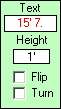
If the text distance in the Text box is in red, it has been calculated between the first two handles you set. If you like, you can edit this text to be anything you might like. If you do so, the resulting label will be shown in black. To return to a machine calculated distance label, just edit the text and use a single + sign for your label.
The Height box controls the size of your label in the dimension line, and the Flip and Turn checkboxes affect its position. Try fiddling with these and you'll quickly see how they work.
![]() Draw Arrow - This button is used to add an arrow to your design. Click two points, as though drawing a line. The arrowhead will be added at the end you click second. A control menu allows you to set the size and angle of the arrowhead.
Draw Arrow - This button is used to add an arrow to your design. Click two points, as though drawing a line. The arrowhead will be added at the end you click second. A control menu allows you to set the size and angle of the arrowhead.
That's the last of the drawing buttons, but some still remain:
![]() Select Line - Even after you have completed a figure such as a circle, dimension line or curve, you can still go back and adjust it. To do this, click the Select Line button, then click on any line that is a part of the figure you want to alter. When you do this, the handles will reappear and you can make any needed modifications. Only lines that are drawn in blue are active for selection and editing. If the line you wish to modify is not drawn in blue, exit from the Drawing menu and right-click on the desired line to load it for editing. Only lines created with the Drawing menu are eligible for editing.
Select Line - Even after you have completed a figure such as a circle, dimension line or curve, you can still go back and adjust it. To do this, click the Select Line button, then click on any line that is a part of the figure you want to alter. When you do this, the handles will reappear and you can make any needed modifications. Only lines that are drawn in blue are active for selection and editing. If the line you wish to modify is not drawn in blue, exit from the Drawing menu and right-click on the desired line to load it for editing. Only lines created with the Drawing menu are eligible for editing.
![]() Delete Line - Should you ever wish to remove one of the lines you have drawn, click the Delete Lines button and then the desired line. It will turn bright red. Clicking the line a second time will cause it to be removed. As with the Select Line command, only blue lines are eligible for removal.
Delete Line - Should you ever wish to remove one of the lines you have drawn, click the Delete Lines button and then the desired line. It will turn bright red. Clicking the line a second time will cause it to be removed. As with the Select Line command, only blue lines are eligible for removal.
![]() Grid On/Off - Clicking this button turns the Design Editor's grid on and off. Right-clicking allows you to adjust the grid to your liking. If the grid is on, the program will automatically snap to grid points as you draw, unless you hold the Shift key as you click or set the snapping attraction strength to a value less than the resolution of the grid.
Grid On/Off - Clicking this button turns the Design Editor's grid on and off. Right-clicking allows you to adjust the grid to your liking. If the grid is on, the program will automatically snap to grid points as you draw, unless you hold the Shift key as you click or set the snapping attraction strength to a value less than the resolution of the grid.
![]() Guide Picture On/Off - Sometimes you may have a jpg or bmp picture you would like to trace using the Drawing commands. Click the Guide Picture button to turn such art on and off as you work. Right-click this button to set up a guide picture.
Guide Picture On/Off - Sometimes you may have a jpg or bmp picture you would like to trace using the Drawing commands. Click the Guide Picture button to turn such art on and off as you work. Right-click this button to set up a guide picture.
Note: it is best to use a picture that is about the size of the drawing area. The ideal size is given when you set up your picture. Zooming does not affect the guide picture, which can be a little frustrating. In such cases, you may want to set up your guide picture as a background picture before proceeding to the Draw menu.
![]() Handle Size - If you find you are missing the handle circles frequently as you work, or if they are to large, you can adjust their size to suit by clicking this button.
Handle Size - If you find you are missing the handle circles frequently as you work, or if they are to large, you can adjust their size to suit by clicking this button.
![]() Attraction - If you click close enough to another point in the design while doing your drawing, or if you click close to a grid intersection, the new point will be snapped onto the old point or grid intersection. When does this happen? That depends on the attraction value, which you can modify this using the Attraction button. The lower the value you choose, the closer you will have to be to another point in the drawing before snapping will occur. When you are very sure you do not want any snapping at all, hold the Shift key as you click your points.
Attraction - If you click close enough to another point in the design while doing your drawing, or if you click close to a grid intersection, the new point will be snapped onto the old point or grid intersection. When does this happen? That depends on the attraction value, which you can modify this using the Attraction button. The lower the value you choose, the closer you will have to be to another point in the drawing before snapping will occur. When you are very sure you do not want any snapping at all, hold the Shift key as you click your points.
At the right of the Drawing screen is a stack of 5 buttons. Two are quickly disposed of:
Cancel abandons all of your drawing efforts and returns you to the main Design Editor screen without saving anything.
Help displays this help.
The top two buttons are also easy:
Save as Lines saves whatever you have drawn as lines that will added to your design.
Save as Icon is much the same as Save as Lines, except the lines you have drawn will not appear in 3D views based upon your design, only in flat 'plan' representations. This is useful for dimension lines and also in creating certain kinds of 3D furniture where you want to have control over how the piece is displayed in the Design Editor.
... which leaves only one save button to go, but this one is a doozy!
Save as 3D - Piece Creation
See the Making Furniture videos
When you click Save as 3D, a sub menu appears that lets you save your lines as a 3D piece of furniture. There are 5 ways of doing this:
Simple Lines
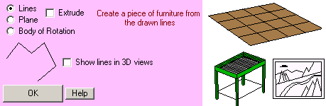
Clicking the Lines radio button and unchecking the Extrude check box causes the menu variation above to be displayed.
Your only choice here is to check or uncheck the Show lines in 3D views checkbox. If you check it and click OK, your drawing will be saved exactly as though you had clicked the Save as Lines button described above. If you uncheck Show lines in 3D views and click OK, your drawing will be saved exactly as if you had clicked the Save as Icon button described above. Look at the pieces to the right of the menu. The crossing lines in the dance floor, the mesh of the grill and the bracing wire between the feet, and the entire picture in the piece of art are just lines such as can be created with this menu variation.
Extruded Lines
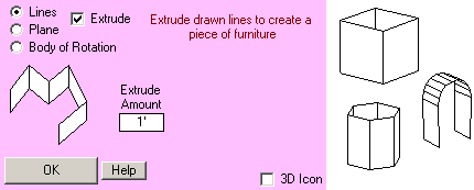
Clicking the Lines radio button and checking the Extrude check box causes the menu variation above to be displayed.
Now when you save your drawing, each element will be extruded away into the screen the distance you set with the Extrude Amount box. Once back at the Design Editor screen, you can use the standard piece sizing commands to change this if you wish.
Normally the icon for an extruded piece is just a single line along the bottom of the 3D piece. If you plan to rotate your piece from a front or side view, you will find it very handy to check the 3D Icon checkbox, as this will allow you to see a better representation of the piece when you return to a top view. A 3D Icon is one where every visible line in a piece is part of the icon PartyCAD uses to represent the piece in the Design Editor.
Look at the pen, lamp shade and wedding arch to the right of the menu above. All of these are very simple examples of extruded lines.
Simple Planes
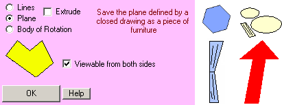
Clicking the Plane radio button and unchecking the Extrude check box causes the menu variation above to be displayed. This is where the fancy stuff begins. If you are an old hand at using PartyCAD, you have no doubt had occasion to use the RUG or PIC pieces in your designs. Now you can create such shapes yourself.
In order to create a simple plane, you must first draw it using the drawing commands. What you do is draw a single closed figure. Anything else, and when you click OK, the program will complain bitterly. There can be no extraneous lines on your drawing. You can use any or all of the drawing commands - arcs, lines, spline curves, whatever - to create the drawing but it must be a single closed shape - one that encloses space on the page.
Usually, if you are working on something that will be at ground level, you will not need a back on your piece, as no one will ever be viewing its underside. In such cases, uncheck the Viewable from both sides checkbox. Doing so will simplify processing when the figure is drawn in 3D. If you are working in a front or side view, this box should probably be checked, so that the shape you create will be visible from all angles.
When you are ready, click OK and the piece will be generated and added to your design, where you can size, move and color it as you would any other piece of PartyCAD furniture.
Extruded Planes
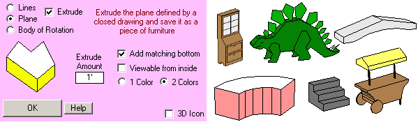
Clicking the Plane radio button and checking the Extrude check box causes the menu variation above to be displayed. The same rules apply as with simple planes, but here, in addition to just generating the plane, the program adds extruded sides, and optionally, a matching bottom.
As before, Extrude Amount controls the amount of the extrusion.
The Add matching bottom checkbox controls if the resulting 3D figure will enclose 3D space. Are you making an oddly shaped stage on the floor? Then no bottom is required. Are you making a set of stairs or some other shape that could be viewed from any angle? Then it needs a bottom or a back.
If you don't expect the user will ever see the inside of your piece, uncheck Viewable from inside, otherwise, mark the checkbox.
You can choose from either a 1-color or a 2-color scheme. In the 2-color scheme, the sides are one color and the top and bottom are the other. If that doesn't suit, you can use the Piece Editor to tweak the coloration of your piece after you return to the the Design Editor.
The 3D Icon checkbox was discussed above and works in exactly the same way here as it did with extruded lines.
Bodies of Rotation
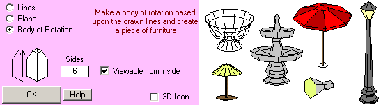
Clicking the Body of Rotation radio button causes the menu variation above to be displayed. This is the most complicated of the furniture generation options. Here, you must draw a vertical or horizontal arrow to indicate the axis of rotation, and then draw a shape that is to be swept through 360 degrees around the arrow to create an object. Complicated though the process may be, you can create some stunning pieces using bodies of rotation.
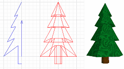
In the Illustration above, the lines that control the generation of the tree are first drawn in a front view of an arrangement. There are just two of them, an arrow and a simple polyline.
The next step was to save the drawing as a body of rotation with 6 sides. The more sides you specify, the smoother will be the finished result, but this does increase the complexity of the piece, and may make rendering take a bit longer.
Once the basic tree above was created, it only took a couple of minutes with the Piece Editor to add the textures and create the final result.
Creating Fancy Pieces
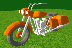
Take a look at this motorcycle. It was assembled in the Design Editor from pieces generated as described above. It took about a day to create and shows that just about anything can be modeled in PartyCAD if you put your mind to it.
The best way to become comfortable with the process of piece creation is to watch Online Videos relating to the subject. Then, you just need to practice. It will take a while to become an expert, but you should be able to create simple pieces pretty quickly once you set your mind to it.
See Also: Piece Editor