|
3D Plan Editor |
  
|
|
3D Plan Editor |
|
Watch the 3D Ballroom online video to learn the basics of 3D plan creation.
Watch the Mastering the 3D Plan Editor online videos to learn more.
Constructing Plans Using the Building Head
Menu Bar - Loading, Save options, 2D/3D conversions, curving walls.
Using a background picture while constructing a 3D plan
Getting Into and Out Of the 3D Plan Editor
There are two ways to get to the 3D Plan Editor:
For New 3D Plans - From the Start Menu, under Create a Project, you click Enter Floorplan. This brings up the following preliminary menu:
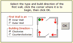
Here you set where your 3D plan will start. Usually is least confusing to start with an inner wall, in the upper left-hand corner, which is the default setting. When you click OK, the 3D Plan Editor then appears.
Once you complete your plan, the buttons at the top change to show more general purpose ones:![]()
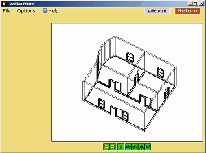
When you are ready, click Save Plan. A 3D preview of the plan will be presented along with various options:
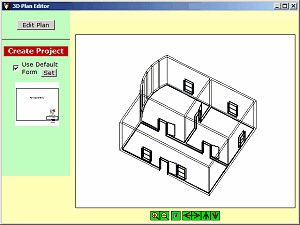
Click Edit Plan to resume editing of your 3D plan if it is not correct. If things look good, click Create Project to create a project and bring up your plan in the Page Editor. Or, click ![]() at the upper right to abandon your plan and return to the Start Menu.
at the upper right to abandon your plan and return to the Start Menu.
When Revising Old Plans - from the Design Editor, if your plan is a previously created 3D plan, you can edit by clicking ![]() , the Edit Plan button. Again, the 3D Plan Editor is displayed, but this time it shows your plan ready for editing.
, the Edit Plan button. Again, the 3D Plan Editor is displayed, but this time it shows your plan ready for editing.
When you have made the desired changes, click Save Plan. A 3D preview of the plan will again be presented along with various options:
Click Edit Plan to resume editing, or if things look good, click Return to create a project and transfer control back to the Design Editor. Or, click ![]() at the upper right to abandon your changes.
at the upper right to abandon your changes.
Floorplans consist of walls, windows and doors. Anything else that you might want to add, things such as stairs or supporting columns, are added as furniture using the Design Editor.
Although you build your plan using a 2D view, the data you enter allows the program to create a 3D model when it is saved to disk.
The 3D Plan Editor is very easy to use if you are working from a sketch that includes dimensional information about the walls, windows and doors of an actual space. You can collect this data by measuring the rooms, or from architect's plans. If you are designing your dream house, the editor can be frustrating to use because of its constant need for sizes. In such situations, it is best to start with pencil and paper, and only come to the editor once you have a pretty good idea what you want to create.
Constructing Plans Using the Building Head
![]()
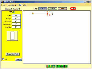
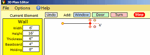
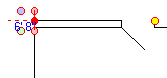
When Make Plan is in drawing mode, the head of the item currently being constructed is decorated with a number of dots. These are used to control the construction process. If you are building a wall, the dots look like the illustration above. Drag on the solid red dot to changes the length of the wall. As you do this, the reported length of the wall changes, as does the Width value in the Wall menu at the left of the screen. Another way to change the length of the wall is to change this Width value directly. This is handy if you need to make big change that will take you out of the displayed window of the plan. The Wall menu also allows you to change other characteristics of the wall, most importantly the wall height, which you should set immediately when you begin entering data for a new plan. More on this below.
Once your wall is correct, click on one of the other dots to complete it and move on to the next element of the plan. Clicking on the pink dots makes a turn to the right or left. Clicking the green dot creates a door, and the blue one makes a window. Notice that these colors match the labeled buttons at the top of the screen, which can also be used to move on to the creation of the next element of a plan.
![]()
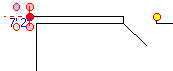
If you are building a window or door, the head is much simpler, just a red dot to drag to change the width, and near by, a yellow dot to click when you are ready to move on to the next wall. Every window and door in the plan must have a wall on either side of it. Usually this is true anyway since the trim around a door or window does not count in its width. If you ever really need to have a window or door tight to another or to a corner, just use a very, very short wall ---- say .1" in length.
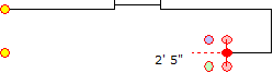
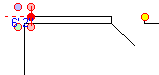
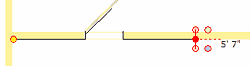
As you continue building your plan, you will eventually turn in the general direction of the ending point and yet another yellow dot will appear. In the illustration above, clicking on the lower yellow dot will lengthen the wall so that it ends exactly under the place where the room began. If you were then to click on the upper yellow dot, a second wall would be drawn from that point back to the start point, thus completing the room. Always use the yellow dots to complete your rooms, as this results in more precise models than if you entered a dimension directly.
You can also click on existing walls in your plan to cause a wall that is being built to be lengthened or shortened to an imaginary point of intersection. This is a very good trick to know. For instance if your plan looked like this:
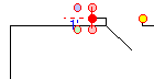
clicking on the vertical wall at the left would cause the screen to change to this:
This trick will save you lots of time fooling with measurements ---- and there is more. If you click in the same place on the vertical line a second time, the screen changes to this:
Finally, a third click in the same place will give this:
These last two techniques are good for situations where the wall you are building needs to be a wall thickness longer or shorter than the intersection with the selected wall. This often happens when building outside wall by hand, though, if you are lucky, you will never have to do this.
Using the building head and the various tricks with dots and lines, you should be able to produce a plan in very short order if your sketch is accurate and complete.
![]()
While you are constructing a room, the buttons above are available at the top of the menu. These do much the same things as using the dots described above, but in addition, ![]() can be used to undo a mistake, and
can be used to undo a mistake, and ![]() can be used to turn in directions other than 90 degrees. This same Turn button can also be used to force the segmentation of a wall, which is occasionally useful when constructing plans containing curved walls.
can be used to turn in directions other than 90 degrees. This same Turn button can also be used to force the segmentation of a wall, which is occasionally useful when constructing plans containing curved walls.
Clicking the ![]() button prematurely terminates the construction of the room. Don't worry though, you can always resume drawing at a later time through use of the Draw button described later on.
button prematurely terminates the construction of the room. Don't worry though, you can always resume drawing at a later time through use of the Draw button described later on.
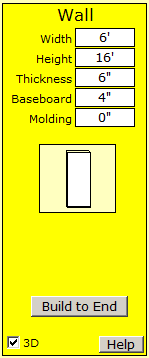
The Wall panel appears at the left of the screen whenever you are constructing or editing a wall. Boxes within the menu allow you to change the Width, Height and Thickness of the wall. Changes in Height and Thickness will not be readily apparent on your plan, but are reflected in the wall preview picture at the center of the Wall panel.
Additionally, you can change the height of Baseboards and Moldings that are to be included as part of the wall. Baseboards are measured from the floor, and moldings from the ceiling. Again, the values you set are reflected in the preview that is part of the panel.
To change the color of the wall, click on the 3D preview picture and select a color using the Color Selection menu.
Six inches is a usual wall thickness in the US, though many times, exterior walls are thicker than interior ones. In such cases, you can just ignore that fact, or change the wall thickness as you go, or wait until the entire plan has been entered and then edit the thickness of outside walls and windows prior to generating the outside walls. It is easiest to just ignore the problem and use one wall thickness throughout, if this is acceptable in a given situation.
When a Match to End button is visible, clicking on this will lengthen or shorten the wall currently under construction so that it is matched to the ending point of the room. That is, the end of the wall will be at a right angle to the ending point of the room. This is helpful if square corners are important.
Clicking the Build to End button will cause the program to turn toward the ending point of the room and then build a wall of exactly the correct length to reach that point.
Unchecking the 3D check box at the bottom of the Wall panel will cause just a 2D version of the wall to be created during saving. This is rarely used as the View Editor can flatten plans for you automatically.
Note: if you set the molding height of a wall, window or door to 99, not only will no molding be created for the wall, but the top of the wall will be made invisible. This is handy if you have varying height walls in a room. Just make the top lines invisible and the add lines of the proper height to represent the wall tops in the Furnish program. Usually you will want to use the piece of furniture called HLINE (horizontal line) under Basic Pieces to do this.
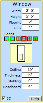
Similar to the Wall panel above, the Window panel appears whenever you are constructing or editing a window. Boxes allow you to set the Width and Height of the window, in addition you can set the FloorHt - the distance from the bottom of the window to the floor. A Trim box allows you to set the width of the trim around the window. Trim is not considered part of the width, and so it is important to have walls of sufficient width on either side of a window if the trim is to show correctly. The remaining value boxes have the same meaning and usage as in the Wall Panel above.
To change the color of a window, click on the 3D preview picture and select a color using the Color Selection menu.
The buttons in the Panes section allow you to select from a variety of window types, or you can just make a hole in the wall and add a window as a piece of furniture ---- check in the Design Editor for the available window types. Click the panes buttons and look at the preview window to see the effect of each. One of these buttons deserves just a few more words. The Alcove button at the right creates an alcove, which is just a window with a solid back.
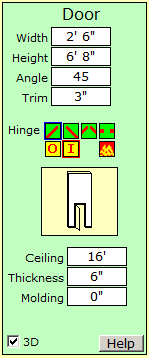
Similar to the panels already covered, the Door panel appears whenever you are constructing or editing a door. Boxes within the menu allow you to set the Width and Height of the door, and the Angle it is to be opened to. You can also set the width of the Trim around the door frame. If you change the open angle, this is reflected in the 2D plan view, not the preview picture. As with windows, the trim is not considered part of the width of the element, and so it is important to have walls of sufficient width on either side of a door for the trim to show correctly. The remaining value boxes have the same meaning and usage as in the Wall element described above.
To change the color of the door, click on the 3D preview picture and select a color using the Color Selection menu.
The buttons in the Hinge section allow you to choose from a variety of door hinge configurations. If you choose the Opening type of hinge, you can add a door as piece in the Design Editor, if you like. Check the Furniture Gallery for possibilities.
The O and I buttons in the Hinge section control if the door is to swing Out or Into the room under construction.
The Fireplace button at the bottom-right of this section causes a door with a solid back to be created. Make this short and wide and you have a fireplace.
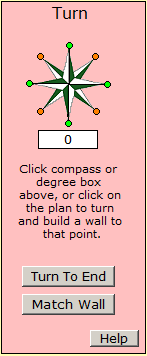
The Turn panel appears when you click the ![]() button at the top of the screen during construction.
button at the top of the screen during construction.
Click on a point of the compass rose to start building in a common direction. If you need to build in some other known direction, this heading can be typed into the direction box beneath the compass rose.
Another way of setting direction here is to just click on any place in the plan area other than the dots of the build control. This causes a turn to be made and a wall built to the point you click. This is especially handy when building over top of a background picture of a plan that contains oddly angled walls.
Clicking the Turn To End button will point the building operations toward the ending point of the room.
One last way to set the building direction is to click on any wall in your plan. Click Match Wall then click near the end point of any line in the 2D plan. Depending on which end of the wall you are nearest to when you click, the building direction will be set to match or reverse the direction in which the wall was built. This is a good trick if you have a lot of oddball angles to deal with in creating a plan.
![]()
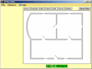
When you leave construction mode, either by completing a room or by clicking the Stop button, a new set of buttons appears at the top of the menu. These allow more general control of the 3D plan creation process.
Draw - click this add more walls, window and doors to your plan. You will be asked to specify the starting and ending points of the series of elements you wish to add. To do this, the program finds every point in the plan that is unconnected with a neighbor. You click on one of these as your starting point. Next, every possible ending point is indicated, and you select one of these. Having done that, the program enters construction mode and the first wall in the series is displayed. Now you just start building until you get to the ending point.
Often, with rooms after the first, you will have to use Draw more than once to complete a room. Just build from one completed element (usually a door) to the next around the perimeter until the room is complete.
Typically, you should not bother with building the outside walls of a plan. Just keep adding onto the interior doors until all of the insides of the rooms are complete, then use the button Outside Walls button to automatically construct the outside walls.
Note: One of the options in Draw setup is Start New. Click on this if you have a room that is disconnected from the rest of the plan. For instance, if your have a hallway running all the way around a central core of rooms.
Outside Walls - adds or removes automatically generated outside walls to/from your plan. Adding outside walls causes the program to analyze your plan and automatically generate the outside walls. This is a very tricky process and the command will not always produce a perfect result. For best results, create all of the room interiors before using this command. If the outside walls generated by this button are less than perfect, use the Delete Item button to delete bad walls and create these parts manually using Draw.
You can also delete all the automatically added walls from your plan, though you will not typically want to do this unless you spot a major error in your plan.
Color - clicking this brings up a Color menu where you can change the colors and textures of any or all of the walls in your plan. Also, you can set the colors of all doors, as well as the colors of the ceilings and floors that are automatically generated by the program. Doors and windows cannot have textures applied, only solid colors, but the color of everything else can be a imported texture... usually a suitably edited picture of the wallpaper of a room. See Color Menu
Edit - clicking this allows you to select and change any item in the plan. If you change the lengths of walls, you will have to edit related items as well. In such cases it is often easier to delete the parts that will change and just rebuild that section of the plan. For most other item values, a simple change will suffice. To quickly switch items while in Edit mode, press the N (for Next) or B (for Back) keys on your keyboard. When you have completed the editing of items, click on OK to leave Edit mode
Move - clicking this button starts a dialog wherein you drag a box around a portion of the plan and then click a "move pad" to shift the points you have boxed. This is often a handy way to shift a window or door along a wall, though you should not have to do this very often if your original measurements are accurate. Move can also be used to increase the width of some rooms. When things look right, click on OK to leave the menu.
Note: It is a good idea to save your project before working with Move, as a mistake here can really mess things up. If you spot such a mistake right away, a Cancel button allows you to escape. However, if you don't spot a mistake until later, you will really wish you had that backup.
Delete - clicking this button starts a dialog where you click on, or drag a box over parts of the plan you want to remove. When you do this, the selected parts are redrawn in red. Clicking on a red item will deselect it. Once the desired items have been selected, click OK to remove the red elements from the plan. A Cancel button is also available, so you can change your mind about deleting any items. Again, backups are good if you are in doubt about deleting elements from your plan.
![]()
These buttons appear below your plan and can be used to zoom in, zoom out, pan a zoomed in view and to refresh the view of your 2D plan on the screen.
![]()
File
The following commands appear under the File item on the Menu Bar:
Background Picture - allows you to specify a picture that will be displayed in the background as you build your 3D floorplan. See the Multi-Room 3D Plans online video for a demonstration of this technique.
Hide Background Picture - temporarily hides the background picture.
Save as Furniture - Normally, plans you create in the 3D Plan Editor become the plan associated with a project. In some circumstance, however, you may want to treat the plan as a piece of furniture, to be arranged on a larger rectangular plan as you would any other piece. This option allows you to do just that.
Exit - terminates the 3D Plan Editor without saving your work.
Options
The following commands appear under the Options item on the Menu bar:
Dot Size - allows you to make the dots used during construction larger or smaller.
Show Grid/ Set Grid - use these entries to set up and display a grid that may aid you in positioning free standing parts of the plan such as core offices.
Check Geometry of Plan - in order for the program to automatically create floors, ceilings and wall tops, the geometry of your model must be complete. This just means you must complete all of the walls of your plan, including outside walls. Clicking this item causes an analysis to be done to verify the completeness of your plan. If it is not complete, problem areas will be indicated.
Set Ceiling Height - allows you to set the height of the ceiling of the entire plan by entering a single value. This is handy if you forget to set the correct ceiling height when you start making a new plan and later realize that the ceiling is too low or too high.
Curve a Wall - causes a dialog to start that allows you to curve any wall in your plan. If you complete the process, the straight wall you select will be replaced by a series of straight segments that approximate a curved wall. This is a seldom used option, but, when you need it, you really need it. The turn to match option of the Turn Panel may also be useful in working with curved walls.
The Build Outside Walls command will build outside walls for a curved wall, but these walls are distorted and incorrect. The problem becomes more evident as the curvature of the wall increases. The remedy is to not curve your wall until after outside walls have been added to the plan, then curve both the inner and the outer walls in separate operations.
If you want to curve just part of a straight wall, segment the wall and curve the desired segment. You can force the segmentation of a wall by clicking the Turn button and then setting the building direction to equal the direction you were already building in.
Open 45 Degree Doors in 3D Model - checking this option causes all of the doors in your plan that are opened to 45 degrees to be opened to 170 degrees in the 3D model. This makes it easier to walk around the plan in virtual reality. In some cases opening a door to 170 degrees will cause the it to penetrate a wall or another door. In such cases simply edit the door to change the open angle to a more reasonable value. Any open angle other than 45 degrees will be retained in the 3D model.
Add Wall Tops to 3D Model - checking this option causes a brown top to be generated for each wall in your plan. This makes the model prettier in virtual reality when viewed from above.
2D/3D - this seldom used options causes a popup menu to appear that allows you to convert your entire plan to 2D or 3D items. This can be useful if you have set parts of your plan to 2D for easier viewing and now want to return to a pure 3D
Save Current Values as Defaults - causes the current values for door, window and wall characteristics as the default values.